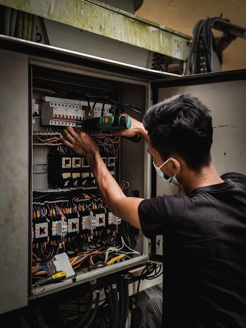
Manual transfer switch wiring diagrams provide a guide to installation, including power source and load sections, using standard symbols and notation, making it easier to understand and implement the switch correctly always.
Understanding the Basics of Manual Transfer Switches
Manual transfer switches are essential components in electrical systems, allowing for the safe and efficient transfer of power from one source to another. They are commonly used in backup generator systems, enabling the seamless transition of power from the utility grid to the generator. To understand the basics of manual transfer switches, it is crucial to familiarize oneself with the different types of switches available, including single-pole, double-pole, and three-pole switches. Each type of switch has its unique characteristics and applications, and understanding these differences is vital for proper installation and operation. Additionally, manual transfer switches come in various sizes, including 30-amp, 40-amp, 50-amp, and 60-amp models, each designed to handle specific electrical loads. By grasping the fundamentals of manual transfer switches, individuals can ensure safe and efficient electrical system operation, and make informed decisions when selecting and installing these critical components. Proper understanding of manual transfer switches is essential for maintaining reliable electrical power supply.

Importance of Wiring Diagrams for Manual Transfer Switches
Wiring diagrams are crucial for safe and correct manual transfer switch installation and operation always using standard symbols and notation for clarity and accuracy purposes only.
Types of Manual Transfer Switches and Wiring Diagrams
There are several types of manual transfer switches available, including single-pole, double-pole, and three-pole switches, each with its own unique wiring diagram and installation requirements. The wiring diagrams for these switches are typically provided by the manufacturer and include detailed information on the connections between the power source, load, and switch. Reliance manual transfer switch wiring diagrams, for example, include diagrams for 30-amp, 40-amp, 50-amp, and 60-amp models, making it easier to find the right diagram for a specific application. Additionally, some manual transfer switches may have additional features, such as auxiliary contacts or pilot lights, which must be taken into account when reading and understanding the wiring diagram. Overall, understanding the different types of manual transfer switches and their corresponding wiring diagrams is essential for safe and correct installation and operation. This knowledge can help ensure that the switch is installed and used correctly, minimizing the risk of electrical shock or other hazards.

Components of a Manual Transfer Switch Wiring Diagram
Manual transfer switch wiring diagrams include power source, load, and switch, using standard symbols and notation, making installation easier always with proper connections.
Power Source and Load in Manual Transfer Switch Wiring Diagrams
The power source and load are essential components in a manual transfer switch wiring diagram, as they determine the flow of electrical power.
The power source is typically the utility grid or a backup generator, while the load refers to the electrical devices and appliances being powered.
In a manual transfer switch wiring diagram, the power source and load are usually represented by distinct symbols, making it easier to identify and connect them correctly.
The diagram will also show the wiring connections between the power source, load, and switch, allowing for a safe and efficient transfer of power.
Understanding the power source and load in a manual transfer switch wiring diagram is crucial for ensuring a reliable and efficient electrical system.
By carefully examining the diagram, individuals can identify potential issues and take corrective action to prevent power outages and electrical hazards.
Proper installation and wiring of the power source and load are critical to the overall functionality of the manual transfer switch.
The diagram provides a clear and concise visual representation of the electrical system, making it an indispensable tool for electricians and homeowners alike.
The power source and load are interconnected, and any issues with one component can affect the entire system.
Therefore, it is essential to carefully follow the wiring diagram and take necessary precautions when working with electrical systems.
Reading and Understanding Manual Transfer Switch Wiring Diagrams
Manual transfer switch wiring diagrams are read using standard symbols and notation, requiring attention to detail and understanding of electrical terminology always correctly.
Identifying the Type of Switch and Its Wiring Diagram
To properly install a manual transfer switch, it is crucial to identify the type of switch being used, as different switches have unique wiring diagrams. The wiring diagram for a single-pole switch will differ from that of a double-pole or three-pole switch; Understanding the switch type is essential to reading and understanding the wiring diagram. The diagram should clearly show the connections between the power source and the load, as well as any additional components such as fuses or circuit breakers. By identifying the type of switch and its wiring diagram, individuals can ensure that their manual transfer switch is installed correctly and functions as intended. This step is critical in ensuring the safe and efficient operation of the switch and the overall electrical system. A correct identification of the switch type and its wiring diagram will also help to prevent any potential electrical hazards or errors.

Applications of Manual Transfer Switches and Their Wiring Diagrams
Manual transfer switches are used in various applications, including backup power systems, portable generators, and home wiring, requiring accurate wiring diagrams for safe installation and operation always.
Connecting a Portable Generator to House Wiring with a Manual Transfer Switch
To connect a portable generator to house wiring with a manual transfer switch, it is essential to follow the wiring diagram carefully. The diagram will show the connections between the generator, the transfer switch, and the house wiring. The transfer switch is typically installed near the main electrical panel, and the generator is connected to the switch using a suitable cable. The switch is then connected to the house wiring, allowing the generator to power the house in the event of a power outage. It is crucial to ensure that the wiring is done correctly to avoid any electrical shock or damage to the equipment. The wiring diagram will provide a step-by-step guide on how to connect the generator to the house wiring using a manual transfer switch, making it easier to install and use the system safely and efficiently. The diagram will also show the various components involved, including the generator, transfer switch, and house wiring, and how they are connected to provide a reliable backup power system.

